-
Products
-
-
 Mobile Machinery Cylinders
 Industrial Engineering Cylinders
 Offshore Cylinders
 Energy Technology Cylinders
 Tunnel Boring Machine Cylinders
-
-
-
-
-
-
-
-
-
-
Offshore Hydraulic SystemHeavy Industry Hydraulic System
-
-
-
-


 Directional Valve
  Pressure Valve
  Flow Valve
  Proportional/Servo Valve
  Cartridge Valve
  Other
Other  Solenoid On/Off Controls
  Electro-Proportional Valves
  Pressure Controls
  Directional Controls
  Flow Controls
  Logic Valves


-
Products

-
Hydraulic Cylinders
-
Mobile Machinery Cylinders
-
Industrial Engineering Cylinders
-
Offshore Cylinders
-
Energy Technology Cylinders
-
Tunnel Boring Machine Cylinders
-
-
Hydraulic Pumps
-
Hengli Piston Pumps
-
InLine Piston Pumps
-
-
Hydraulic Motors
-
Fixed Displacement Motor
-
Variable Motor
-
Radial Piston Motor
-
-
Mobile Control Valves
-
Multi-way Control Valves
-
Pilot Control
-
Motion Valve
-
-
Industrial Hydraulic Valves
-
-
Cartridge Valve
-
-
Orbital Motor
-
HCW
-
HCG
-
HCP
-
HSD
-
HRD
-
HDL
-
HBK
-
HCLB
-
HVA
-
HBA
-
HCL
-
HSP
-
SB4-L1X28
-
-
Electronic Control
-
-
Hydraulic Systems
-
Offshore Hydraulic System
-
Heavy Industry Hydraulic System
-
Test Benches
-
-
High Precision Cast Iron
-
-
Thermal Spray
-
-
-
Applications
-
Mobile Machinery
-
Construction Machinery
-
Material Handling
-
-
Agricultural Machinery
-
Harvesting machinery
-
-
Industrial Engineering
-
Metallurgical Die Casting
-
-
-
-
-
-
Offshore
-
Marine Engineering Equipment
-
Offshore Platform
-
Port Machinery
-
-
Energy Technology
-
Oil and Gas Extraction
-
New Energ
-
-
Tunnel Boring Machine
-
Tunneling Equipment
-
Tunnel Reinforcement
-
-
-
About Us
-
News
-
Service
-
Global Webs


 Product Advantages
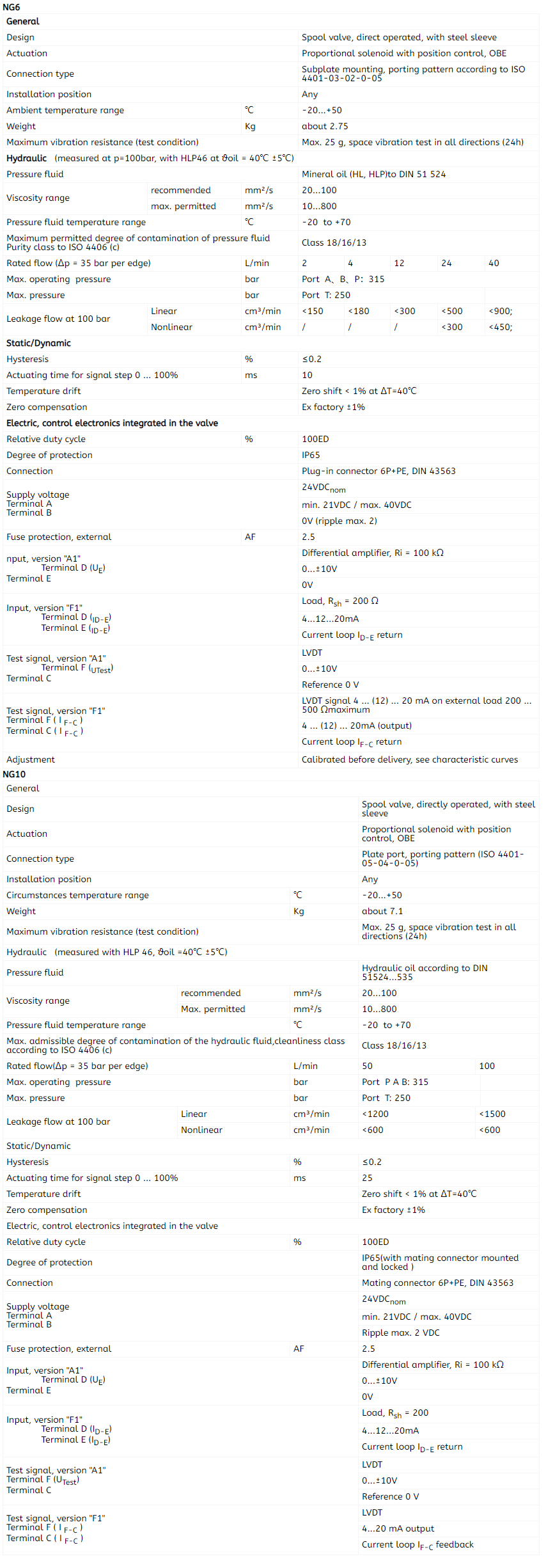
 Technical Specs